More Wings........
- LHE Motorsports

- Mar 23, 2019
- 2 min read
For sake of comparison, a look at some wings in practice in the real world.......
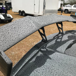
Porsche GT3
Note how the angle slowly changes with the angle of the rear window. The spoiler below the wing helps force airflow closer to the underside of the wing. The wing has a relatively low angle of attack. Also, note how little mount material is attached to the underside. This is likely highly efficient design, but probably does not produce a huge amount of absolute downforce.
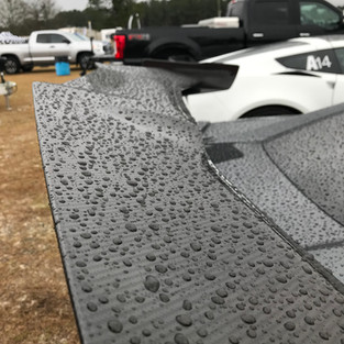
Corvette ZR1
In contrast to the GT3 wing, the ZR1 wing has a very steep angle, and a far less pronounced curvature to the underside. There is far more material on the mounting system. The element does account for the different flow characteristics of the rear hatch, and also utilizes a lip spoiler to help force flow closer to the underside of the wing. In contrast to the GT3 design, this wing is likely inefficient (high drag due to steep angle), but will result in significant downforce at speed.
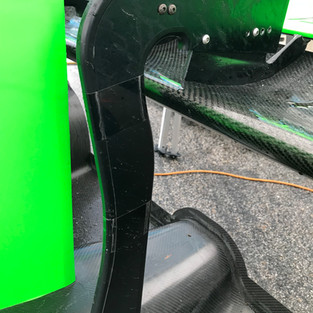
Ginetta LMP3 Prototype
Obviously far more sophisticated than the road cars, with huge endplates and a dual element design. The main element has a relatively shallow angle of attack, but a very pronounced shape to the underside. It also should be noted that the wing is flat; no deviation for cabin airflow. Another critical design element is the use of a swan neck mount. Much care is taken to ensure the underside of the airfoil is undisturbed to maximize downforce.
As a side note, this car is run by Zen Racing here in Atlanta. It is being raced in local club Time Trial events, and is the current lap record holder for NASA Time Trial (unlimited class) with a 1:18. The car was driven by Matt Isbell, a very accomplished racer in the region.

Taking some cues from designs currently in practice, the effect of mounting systems was evaluated. The airfoil used here is the same as previous simulations, with the addition of an arbitrarily sized endplate (endplates increase the effective span of the airfoil, and are an important design element warranting proper analysis, which was foregone here).
Little care was taken designing the two mounts. Rather, the objective here was to evaluate the performance of a simple bottom mount versus a top mount (swan neck). I'm sure proper design of the mounts themselves would change the absolute values, but I doubt the relative impacts of the two designs would change. The effects were somewhat alarming.
The simulations were run at 100 MPH with a 6 degree angle of attack. Effectively, the swan neck design resulted in 25% more downforce, and with 9% less drag. This proves pretty convincingly that ensuring undisturbed airflow on the underside of the element is critical to overall performance.
Next steps are to computationally evaluate the performance benefit of this design on the C5, then look into real world testing of an actual prototype. More to come in the following weeks.......


Comments